
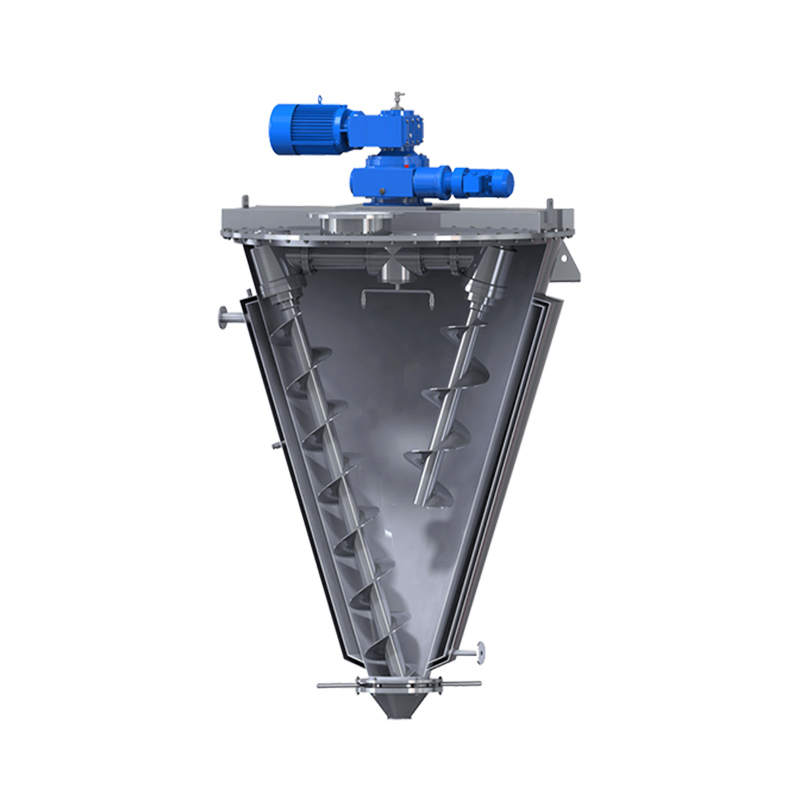
 Conical Screw Mixer
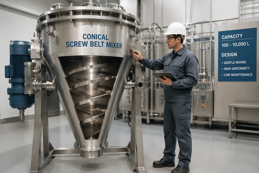
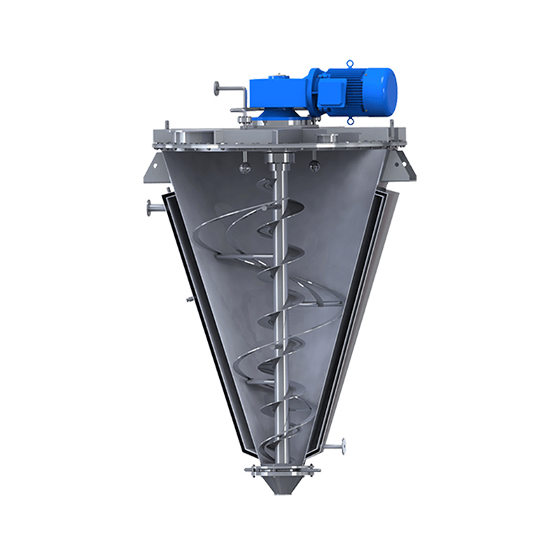 Conical Screw Belt Mixer
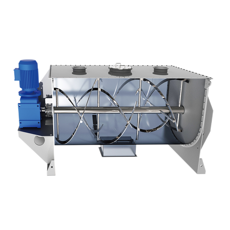 Ribbon Blender
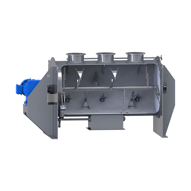 Plough-shear Mixer
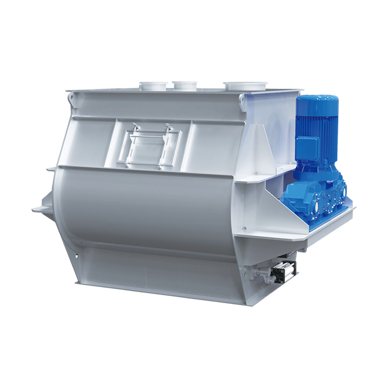 Double Shaft Paddle Mixer
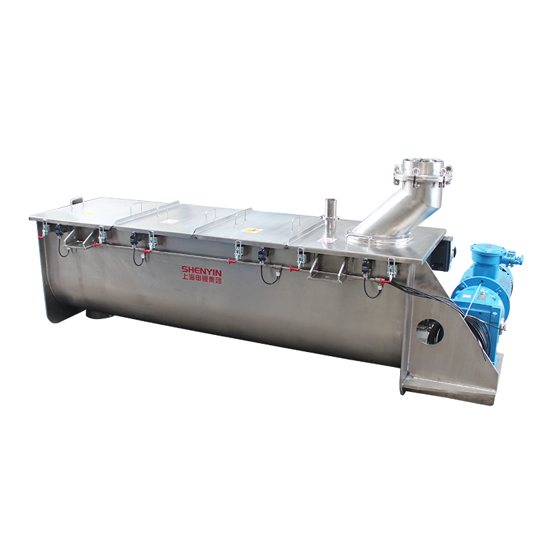 CM Series Mixer


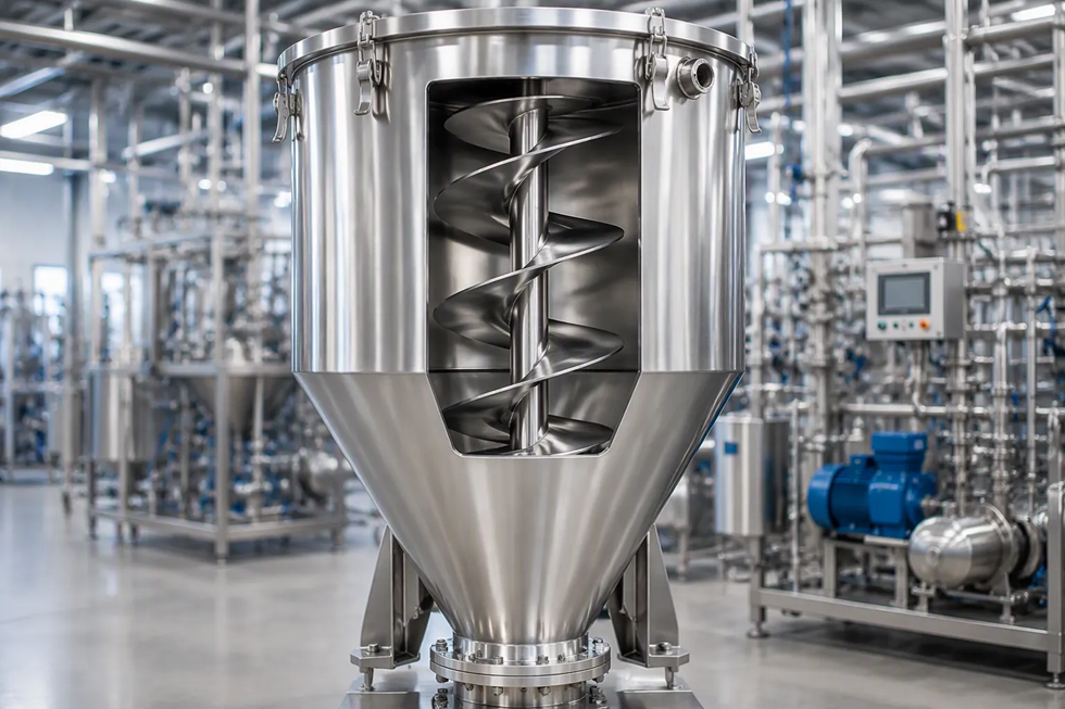
What Key Technical Parameters Should You Evaluate When Buying a Conical Screw Mixer?
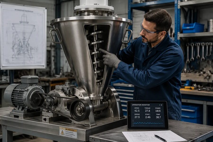
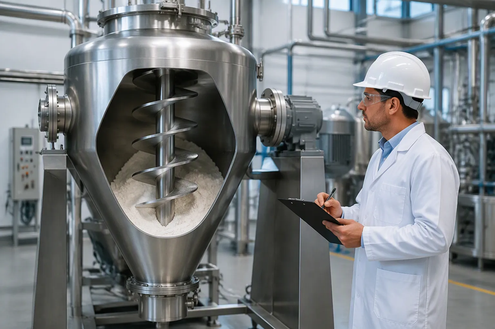
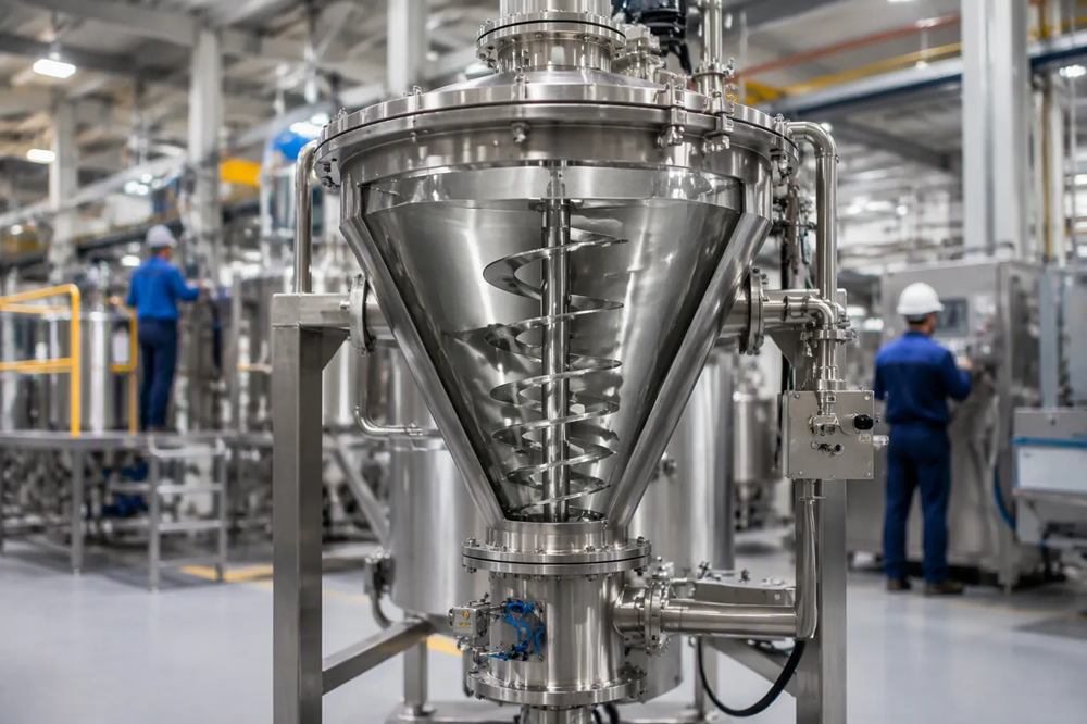
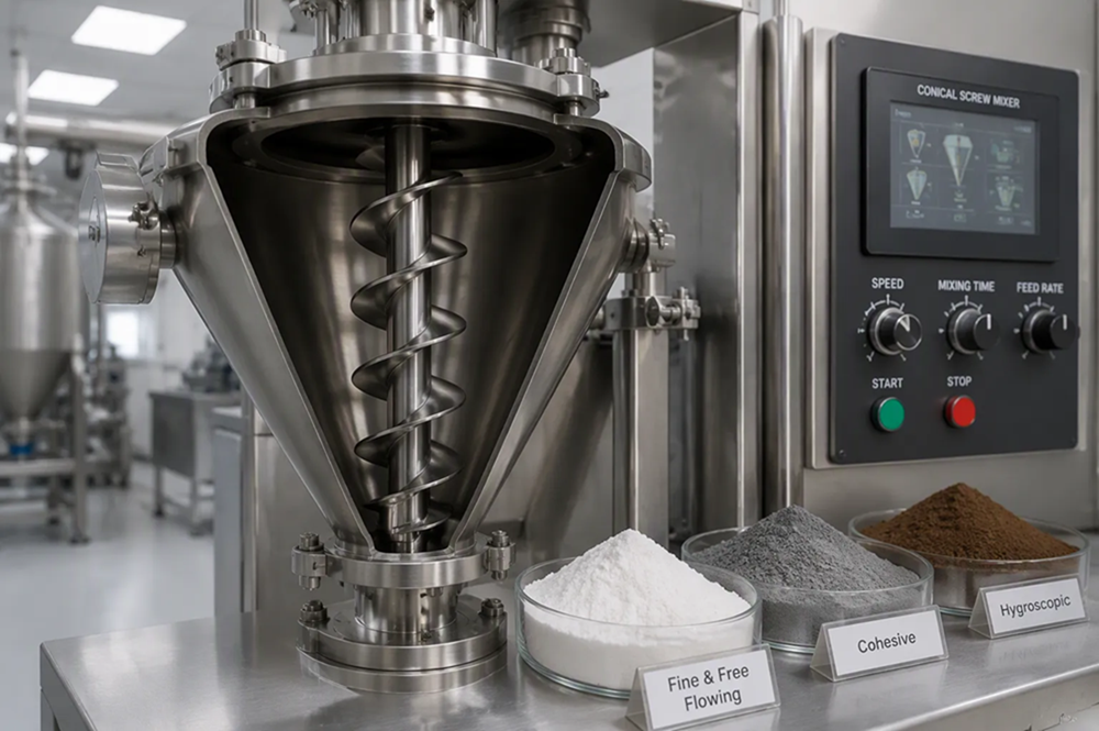
I evaluate working volume from 50–3000 L, rotational speeds, wetted metallurgy like AISI 316 stainless steel, pressure ratings, and shaft seals during technical procurement. Assessing these core engineering specifications prevents costly batch errors. It also optimizes motor efficiency. A cantilevered screw auger uses planetary orbital movement to lift material along the vessel wall. This continuous circulation reduces shear-stress and preserves shear-sensitive powder structures. A minimum efficient load around 30% of working volume maintains batch uniformity up to 1:100,000 ratio. Selecting a Conical Screw Mixer with proper seals and surface finish targets like Ra ≤ 0.4 µm protects product purity and optimizes plant throughput.
- Maintain batch sizes between 30% and 80% of total vessel volume to ensure fast, energy-efficient mixing.
- Choose low screw tip speeds from 0.5 to 2 m/s to protect delicate powders from crushing during processing.
- Select SS316L stainless steel with smooth polished finishes to meet high sanitary standards and prevent product contamination.
- Match motor power and vessel size directly to your ingredient weight to optimize daily energy usage.
Evaluating Conical Screw Mixer Capacity

I always check vessel capacity primary metrics before selecting equipment for plant installations. You must understand the precise distinction between gross vessel volume and active working fill level. Gross volume measures the total internal space of the cone shell. Working volume represents the actual material quantity that your machine processes efficiently during a production batch.
Total Volume vs. Working Fill Level
Equipment datasheets show clear operational differences between total equipment size and actual batch loading limits. Effective active volume typically ranges from 40% to 60% of total gross volume in industrial processing. Many standard production designs set the recommended working volume at exactly 70% of gross volume.
| Model | Gross/total volume (L) | Recommended working volume (L) | Difference (L) |
|---|---|---|---|
| SS-NCM-100 | 100 | 70 | 30 |
| SS-NCM-200 | 200 | 140 | 60 |
| SS-NCM-500 | 500 | 350 | 150 |
| SS-NCM-750 | 750 | 525 | 225 |
| SS-NCM-1000 | 1000 | 700 | 300 |
| SS-NCM-1500 | 1500 | 1050 | 450 |
| SS-NCM-2000 | 2000 | 1400 | 600 |
Loading material outside recommended fill thresholds causes serious operational failures. The Nauta Conical Screw Mixer provides consistent mixing quality across fill levels from 15% to 100%. Operating your equipment within a 30% to 80% filling level range delivers primary process advantages:
- Gravity-driven recirculation moves batch particles constantly along low-shear flow paths.
- Low power consumption keeps motor energy usage low during continuous batching.
- Uniform homogenization occurs rapidly without over-processing fine powder blends.
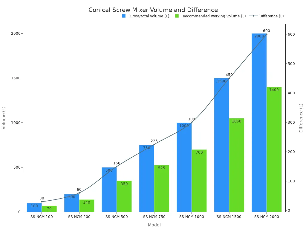
Manufacturers produce standard system models spanning gross volumes from 100 L to 30,000 L. These units deliver working capacities from 50 L up to 10,000 L across food, pharmaceutical, and chemical powder processing lines.
Height Clearance and Footprint
I always measure factory ceiling height and floor footprint early in my equipment evaluation process. Conical units require significant vertical space because the tall cone shape narrows downward toward the bottom discharge valve. Drives mounted on top of the vessel add substantial overhead clearance requirements.
Clear ceiling height must accommodate the complete top drive assembly, the full conical vessel body, and the bottom discharge valve assembly together.
I calculate total space needs by adding top drive maintenance clearance to raw vessel dimensions. Facilities with low ceiling clearance often face installation challenges during equipment mounting. You can install top-mounted drive units through upper floor openings to solve vertical constraints. Alternatively, engineers can integrate lower-profile drive assemblies to fit tight plant layouts.
Large industrial vessels holding up to 30,000 L gross volume demand reinforced floor structural support. You must verify that your plant floor supports the combined weight of the vessel, full liquid or powder charges, and drive motors. Planning these dimensional parameters prevents structural structural modifications during plant integration.
Drive Mechanics and Speed Parameters
Screw and Orbital Arm Velocities
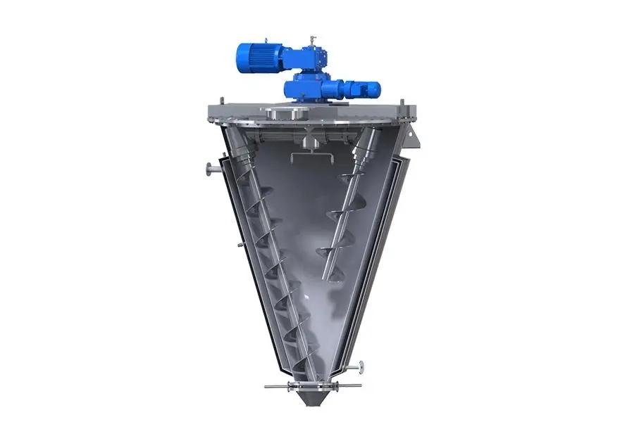
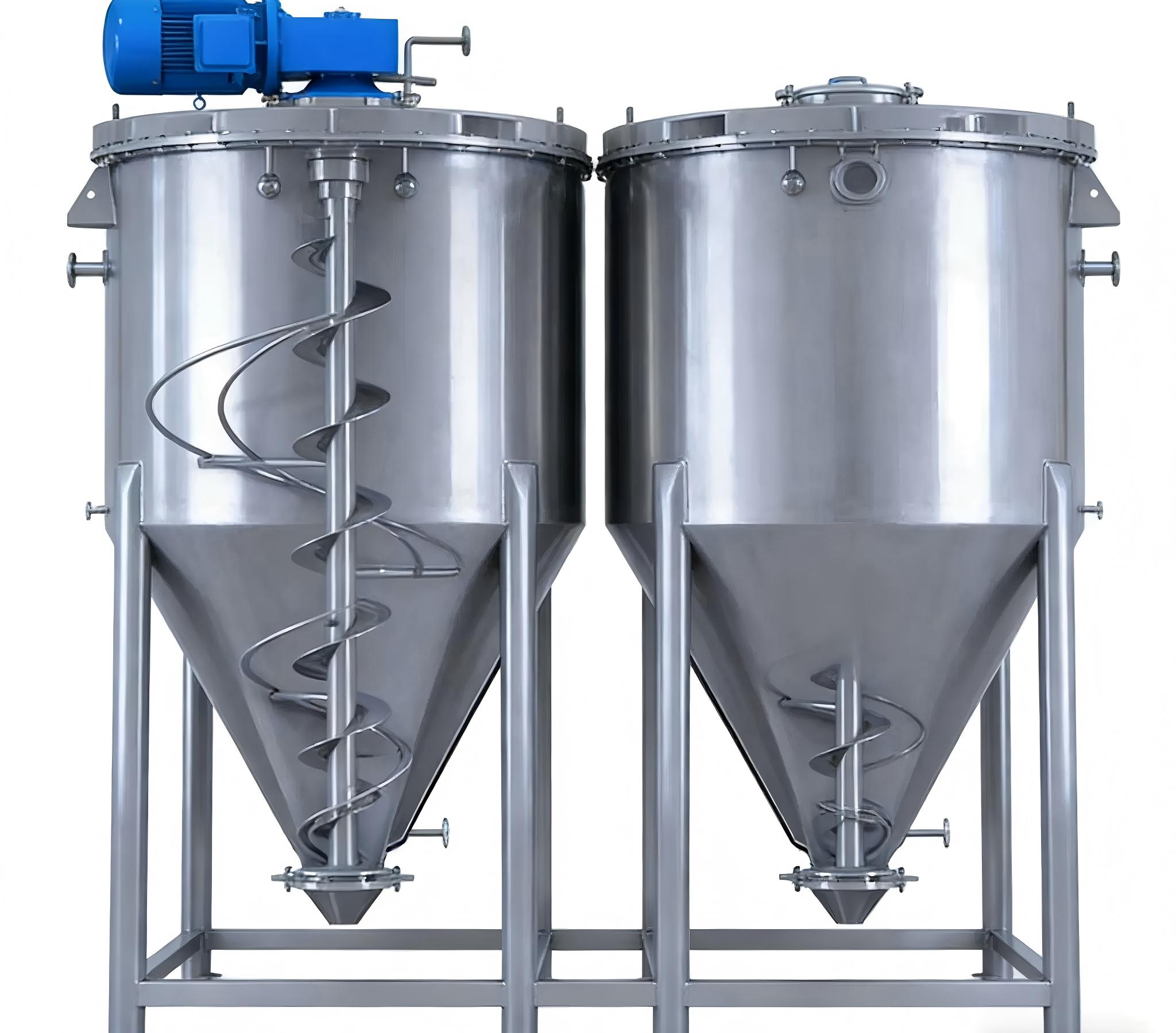
I always evaluate drive mechanics carefully when selecting process blenders for plant operations. Rotational dynamics directly dictate batch homogenizing efficiency and material shear levels. The conical screw mixer relies on two simultaneous mechanical motions to move product smoothly. A vertical screw auger rotates on its own central axis while an orbital arm sweeps that rotating screw along the internal cone wall.
I look for specific velocity parameters during technical equipment evaluations to prevent severe particle degradation. A standard single-screw unit operates with a screw speed around 70 rpm and an orbiting arm speed between 1 rpm and 2 rpm. The resulting screw tip speed stays between 0.5 m/s and 2 m/s. These rotational speeds remain remarkably consistent across various vessel capacities.
| Mixer Vessel Parameter | Standard Operating Specification |
|---|---|
| Screw Rotation Speed | ~70 rpm (or 60 rpm across 285 L to 3,400 L models) |
| Orbiting Arm Speed | 1–2 rpm |
| Screw Tip Velocity | 0.5–2 m/s |
| Twin-Screw Rotation Range | 50–200 rpm |
| Twin-Screw Orbiting Range | 0.5–5 rpm |
I observe that reliable drive systems maintain a fixed proportional relationship between screw rotation and orbital motion. Under high torque processing, an orbital arm gears down from 1.2 rpm to 0.6 rpm while the screw speed gears down from 80 rpm to 40 rpm. This speed relationship maintains an approximate 66:1 mechanical ratio. The low screw tip speed between 0.5 m/s and 2 m/s delivers low-intensity mechanical action. This gentle action prevents delicate powders from hardening or breaking. The screw continuously lifts material from the lower cone apex to the upper surface. Simultaneously, the orbiting arm moves the screw along the cone perimeter. This dual motion exchanges particles along the vessel boundary and eliminates stagnant dead zones.
Motor Power and Energy Efficiency
I evaluate motor power specifications based on working volume limits and material load characteristics. Standard industrial equipment handling working volumes from a 100 L laboratory scale up to over 5,000 L full production capacity requires an installed motor power between 5.5 kW and 37 kW. Lower mechanical friction from gentle screw rotation reduces peak energy demands during initial full-load startups.
Low rotational resistance keeps overall energy consumption low while maintaining high blending precision. A standard mixing cycle completes rapidly within 3 min to 8 min per batch. Short batch durations reduce continuous electrical energy consumption across daily plant shifts. I calculate total power efficiency by assessing drive motor output against complete mixing time. High-efficiency gear motors convert electrical energy directly into gentle axial material movement without producing high frictional heat inside the vessel.
Selecting correct motor sizes prevents severe operational bottlenecks and thermal overloading. Oversized motors waste electrical power during long continuous production runs. Undersized drives suffer excessive mechanical stress when turning dense powder batches. I ensure that the installed motor power range between 5.5 kW and 37 kW aligns with specific bulk density profiles. Aligning drive mechanics with material behavior guarantees consistent power usage and reliable production performance.
Material Rheology and Process Compatibility
Bulk Density and Particle Friability
I evaluate specific powder properties before recommending equipment for continuous mixing operations. I check key material characteristics including bulk density, particle size distribution, moisture content, and angle of repose. I also analyze flow function, compressibility, and lump strength. These detailed physical measurements show how raw solids move inside the vessel.
- Dry powders: Highly compatible with gentle, low-shear blending action.
- Granules: Compatible with uniform processing while protecting fragile structure.
- High-viscosity pastes: Not supported due to heavy resistance against the rotating screw.
The physical state of your ingredient determines overall blending success. I select the conical screw mixer because its slow, gravity-driven circulation protects fragile materials. Fast mechanical blenders crush soft granules into unwanted fine dust. The slow vertical auger gently lifts loose powders without generating High Shear stress. This low-impact lifting action keeps delicate crystalline structures intact during full batch cycles.
Wetted Metallurgy and Surface Finish
I inspect the metal surfaces touching your product to guarantee long equipment life and prevent batch contamination. Chemical exposure and ingredient roughness guide my choice of wetted materials and surface coatings.
| Application / Requirement | Standard Stainless Grade | Typical Surface Finish (Ra) | Protective Surface Treatment |
|---|---|---|---|
| Food & Beverage Processing | SS304 or SS316L | Ra ≤ 0.8 µm | Electropolishing |
| Pharmaceutical Processing | SS316L | Ra 0.4–0.8 µm | Sanitary polishing |
| Abrasive or Saline Powders | SS316L | Ra ≤ 0.8 µm | Nickel or Chrome Plating |
I select SS304 or SS316L stainless steel for standard food processing applications. Pharmaceutical facilities require SS316L stainless steel with a high sanitary finish. Smooth interior walls prevent fine powder particles from sticking to internal vessel boundary points.
I recommend special surface treatments when processing salty, acidic, or abrasive raw solids. Nickel plating increases both corrosion resistance and wear resistance during demanding powder handling operations. Chrome plating improves surface wear resistance and heat tolerance under continuous frictional loads. These protective treatments stop early metal wear and preserve strict sanitary processing conditions.
Thermal Management and Pressure Ratings
Heating and Cooling Jackets
I evaluate heating and cooling jackets whenever a process demands strict thermal control. A heat jacket forms an outer protective shell around the full conical vessel body. This jacket circulates temperature control media like hot water, steam, thermal oil, or cooling liquid. Heat transfers indirectly through the solid vessel wall by thermal conduction. Convection from the moving fluid medium improves heat transfer rates across the entire cone boundary.
I rely on this thermal jacket design to prevent localized hot spots inside thermal-sensitive batches. The rotating screw agitator continuously lifts and folds the powder inside the vessel. This continuous movement exposes every powder particle to the heated or cooled interior wall surface repeatedly. Rapid particle turnover keeps product temperature completely uniform across the entire batch. Thermal jackets excel during dry powder blending, vacuum drying, and temperature-sensitive material processing.
Vacuum and Pressure Operation
I inspect structural pressure ratings when specifying equipment for solvent evaporation, vacuum drying, or pressure-assisted material discharge. Vacuum operations lower the vaporization temperature of liquids trapped inside raw powders. Lowering liquid boiling points allows rapid moisture removal without exposing sensitive ingredients to damaging high heat levels during extended batch runs.
Standard equipment design withstands extreme internal vacuum conditions and high positive internal pressure levels during active processing.
| Parameter | Value |
|---|---|
| Maximum vacuum during drying | Full vacuum down to 0 mbar absolute (-1 bar gauge) |
| Maximum internal pressure for pressure-assisted discharge | +6 bar standard; +10 bar explosion shock-proof option |
Deep internal vacuum pulls moisture out of dense powder beds rapidly during gentle low-temperature drying cycles. Operating personnel can also introduce compressed gas to pressurize the vessel volume. Positive gas pressure drives sticky or dense product batches out through the lower discharge valve assembly smoothly. Selecting certified pressure vessels guarantees operator safety and prevents mechanical vessel deformation under extreme pressure differentials.
Discharge Mechanisms and Shaft Sealing
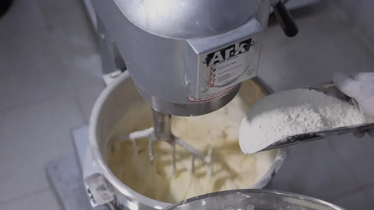
I inspect shaft seals and discharge valves when evaluating equipment for industrial batch operations. Robust sealing components protect raw material charges from external contamination. Efficient bottom discharge valves prevent residual product retention inside the conical vessel body. Proper drive sealing and discharge selection ensure smooth material handling across every batch.
Shaft Seals and Stuffing Boxes
I choose internal shaft seal configurations based on specific processing environment demands and hygiene standards. Effective seal selections stop drive lubricants from leaking into your powder bed during continuous mixing operations. Reliable shaft seals also retain internal pressure or deep vacuum levels during intensive drying cycles.
| Seal Design Category | Options and Configurations |
|---|---|
| Standard Drive Seal | Standard oil seal |
| Sanitary Seal Upgrades | Food-grade grease and oil seal |
| High-Performance Sealing | Mechanical seal |
Standard oil seals perform reliably during basic dry powder processing applications. I select food-grade grease and oil seals for sanitary food and pharmaceutical lines to meet high product safety requirements. Mechanical seals provide maximum isolation against harsh operating environments during demanding chemical processing cycles.
Discharge Valves and Zero-Dead-Space
I inspect bottom discharge valve assemblies to guarantee rapid batch evacuation without leaving unmixed solids inside the cone. The conical vessel geometry and mass-flow structural design feature no internal horizontal surfaces. This steep sidewall profile delivers total gravity material discharge and minimizes valuable product loss across production shifts.
| Discharge Valve Category | Available Valve Designs | Operational Controls |
|---|---|---|
| Standard Primary Valve | Plum-blossom-shaped dislocation valve | Manual or pneumatic control |
| Optional Valve Configurations | Butterfly, ball, star, flap, or gate valve | Electric or pneumatic actuation |
A plum-blossom-shaped dislocation valve fits tightly at the lower terminus of the long spiral screw. This close tolerance placement eliminates mixing dead angles near the lower vessel apex. Operators choose manual levers or pneumatic actuators to cycle the main discharge valve smoothly. I also specify side unloader arrangements, pneumatic outlet valves, or electric butterfly and ball valves to match downstream equipment interfaces.
Selecting the Right Conical Screw Mixer
Operational Configuration and Mounting
I evaluate mounting styles and physical mixer locations during initial plant integration planning. Plant engineers often mount overhead top-entry units onto dedicated structural steel platforms. This overhead mounting configuration supports direct gravity charging from upper floors. Mobile design options allow operators to move smaller vessels easily between raw material loading bays and cleaning stations.
I integrate batch processing sequences directly into central plant automation systems. Proper vessel placement allows smooth material flow from upstream storage silos down to downstream packaging lines. Standard net volume options range from 50 to 5,000 L, while larger industrial units reach up to 10,000 L. Selecting the right structural placement ensures convenient physical access to dedicated access hatches for routine equipment cleaning and maintenance inspection.
Technical Evaluation Checklist
I use a step-by-step decision framework to match raw material properties directly to vendor specification sheets. This systematic evaluation procedure guarantees reliable equipment performance across different production requirements.
| Step | Material Property | Vendor Specification Check |
|---|---|---|
| 1 | Material state (powder, liquid, pasty) | Objective and media type |
| 2 | Batch volume and footprint limits | Net volume (50 to 5,000 L) |
| 3 | Corrosiveness or sanitary standards | Vessel material (SS304/SS316L) |
| 4 | Cleanability and surface release | Surface finish (satin or polished) |
| 5 | Complete discharge requirements | Discharge valve type |
| 6 | Thermal control and safety needs | Heating/cooling jacket options |
I check material shear sensitivity to confirm low-intensity processing needs. A Conical Screw Mixer provides three distinct mixing actions: axial movement along the screw, radial movement along the cone wall, and tangential movement around the orbital arm. This combined motion reaches precise batch homogeneity within 5 to 15 min mixing time without damaging fragile solids.
I verify recipe flexibility and liquid addition requirements during final spec sheet reviews. Installing specialized liquid injection devices allows uniform liquid dispersal into dry powders during active blending cycles. Matching these specific process features to raw ingredient behaviors ensures long-term operational success.
I systematically evaluate volumetric capacity, rotational dynamics, wetted metallurgy, pressure ratings, and sealing mechanisms to select the optimal equipment for plant production lines. Matching these core engineering specifications to raw bulk density and particle friability prevents material degradation and costly batch errors. A Conical Screw Mixer delivers gentle, high-precision blending when process leaders align vessel dimensions directly with real ingredient behaviors.
I encourage every process leader to request pilot testing before finalizing machinery purchases. Running test batches with actual powder samples validates mixing uniformity and cycle times. Plant managers must also verify factory acceptance testing protocols with suppliers to ensure total operational success.
FAQ
I recommend keeping the batch load between 30% and 80% of the total working volume. This fill range allows gravity to circulate particles smoothly. Operating in this zone ensures fast homogenization and keeps motor power consumption low.
I observe that a complete mixing cycle usually takes between 3 min and 8 min. The rotating screw continuously lifts powder while the orbital arm sweeps the vessel wall. This dual action achieves precise blend uniformity very quickly.
Yes, I choose this equipment specifically for delicate powders and fragile granules. The screw tip speed stays low, between 0.5 m/s and 2 m/s. This low-shear movement lifts materials gently without crushing particle structures or generating excessive heat.
I specify AISI 304 or 316L stainless steel for food contact surfaces. I always select AISI 316L stainless steel with a high sanitary finish like Ra ≤ 0.4 µm for pharmaceutical processing. Smooth surfaces prevent powder accumulation and make equipment cleaning easy.